

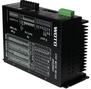
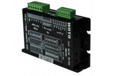
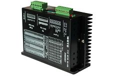
Low Voltage Motor Driver 3DM683
-
Payment


-
Origin
China Mainland
-
Minimum Order
15
-
Packing
Pieces
- Contact Now Start Order
- Description
Product Detail
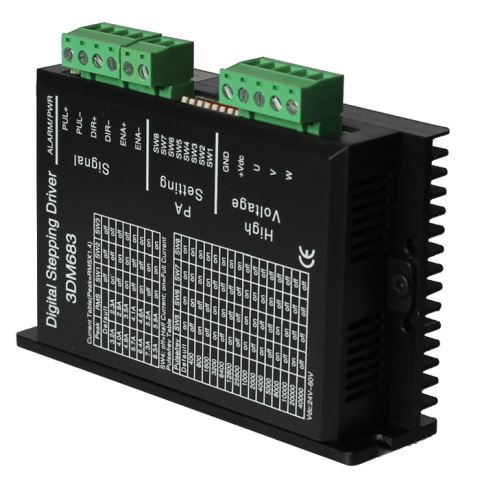
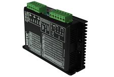
3DM683
Characteristics :
High performance , cheap price ,lower noise .
Can driver three and six wires three phase stepper motors .
Low heating for stepper motors and motor drivers .
Optical isolate input differential singnal
Input singnal TTL compatibility
Current will be half automatically when stand still
8 class subdivision can be chose .
With short circuit, over-voltage, under-voltage, over-temperature protection and improving functions
Stepper Motor driver Specification :
Input Power supply : | 24VDC~60VDC |
Output Current | 2.1A~5.6A |
Drive Way | PWM constant current chopping ,three phase Sine wave output current |
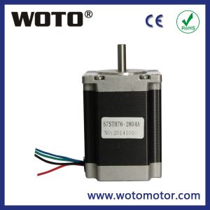
Suitable stepper motor | 57.85 series three phase stepper motor |
Ambient environment | -10?~55? 15~85%RH?No condensation. Non-corrosive, flammable, explosive, conductive gas, liquid and dust |
Keeping enviroment | -40?~+55?, <93%RH,No condensation, no frost |
Size (L*W*H) | 118*75*32 mm |
Net Weight | 0.25 Kg |
Subdivision setting:
Subdivision | SW5 | SW6 | SW7 | SW8 |
Default | on | on | on | on |
800 | off | on | on | on |
1600 | on | off | on | on |
3200 | off | off | on | on |
6400 | on | on | off | on |
12800 | off | on | off | on |
25600 | on | off | off | on |
51200 | off | off | off | on |
1000 | on | on | on | off |
2000 | off | on | on | off |
4000 | on | off | on | off |
5000 | off | off | on | off |
8000 | on | on | off | off |
10000 | off | on | off | off |
20000 | on | off | off | off |
40000 | off | off | off | off |
Default: The number of pulses can be customized .
Current setting :
Peak | RMS | SW1 | SW2 | SW3 |
Default | off | off | off | |
3.2A | 2.3A | on | off | off |
4.0A | 2.9A | off | on | off |
4.9A | 3.5A | on | on | off |
5.7A | 4.1A | off | off | on |
6.4A | 4.6A | on | off | on |
7.3A | 5.2A | off | on | on |
8.3A | 5.9A | on | on | on |
Description :
Microstep setting | Users can set the driver Microstep by the SW5-SW8 four switches.. When you set the microstep , pls stop the driver working?The setting of the specific Microstep subdivision, please refer to the instructions of the driver panel figure . |
Output current setting | Users can set the driver Microstep by the SW1-SW3 three switches. The setting of the specific Microstep subdivision, please refer to the instructions of the driver panel figure.. |
Automatic half current function | Users can set the driver half flow function by SW4. "OFF" indicates the quiescent current is set to half of the dynamic current, that is to say, 0.5 seconds after the cessation of the pulse, current reduce to about half automatically. "ON" indicates the quiescent current and the dynamic current are the same. User can set SW4 to "OFF", in order to reduce motor and driver heating and improve reliability. |
signal Interface | PUL+ and PUL- are the positive and negative side of control pulse signal; DIR+ and DIR- are the positive and negative side of direction signal; ENA+ and ENA- are the positive and negative side of enable signal . |
Motor Interface | A+ and A- are connected to a phase winding of motor; B+ and B- are connected to another phase winding of motor. If you need to backward, one of the phase windings can be reversed . |
Power Interface | It uses DC power supply,recommended working voltage is 24-50VDC,power is over 100W . |
Indicator Lightor | There are two indicator lights. Power indicator is green. When the driver power on, the green light will always be lit. Fault indicator is red, when there is over-voltage or over-current fault, the red light will always be lit; after the driver fault is cleared, if re-power the red light will be off.? |
Installation | The size of motor driver is 118×75×32 mm,mounting holes is 100mm?Chest and upright installation are ok,we suggest upright installation? During installation, it should be close to the metal cabinet for heat dissipation. |
Interface of signal :
Picture 1 : common anode connection

Picture 2 : common cathode connection

Control signal and outer interface :
Signal amplitude | Out-connected limited resistance R |
5V | Not added |
12V | 680O |
24V | 1.8KO |
Normal signal instruction :
phenomenon | cause | ways |
Indicator lighter is red | 1?the wire of stepper motor is short-circuit ? | check or change the motor wire |
2?outer voltage is over or below the range of working voltage | adjust the range of voltage | |
3?unknown reason | Back to check |
Installation size :

-
High Torque Nema 23 Stepper Motor 425 Oz In 1 Pieces / (Min. Order)
-
Nema 23 Stepper Motor 1.26N.m 1 Pieces / (Min. Order)
-
Nema 23 Stepper Motor 1.89N.m 1 Pieces / (Min. Order)
-
110V Stepper Motor Driver 2H1106T 1 Pieces / (Min. Order)

-
220V Nema 34 Stepper Motor Driver 2H2208T 1 Pieces / (Min. Order)
-
Brushless Motor Driver 15 Pieces / (Min. Order)
-
2000W Servo Motor Drivers 15 Pieces / (Min. Order)
-
1500W Servo Motor Driver 15 Pieces / (Min. Order)
-
Driver Stepper Motor 2H606T 15 Pieces / (Min. Order)
-
Three Phase Motor Driver MD-3008B 15 Pieces / (Min. Order)
-
Nema 52 Stepper Motor Driver 3008A 15 Pieces / (Min. Order)
-
Motor Driver For Nema 2M423A 15 Pieces / (Min. Order)
-
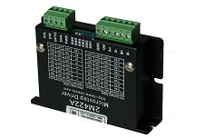
Small Stepper Motor Driver 2M422A 15 Pieces / (Min. Order)
-
220V Motor Driver 2H2208T 15 Pieces / (Min. Order)
-
Motor Driver 2H1106T 15 Pieces / (Min. Order)
-
AC Stepper Motor Driver 2H8006T 15 Pieces / (Min. Order)
-
1.2 Degree Nema 52 Stepper Motor 1303P 15 Pieces / (Min. Order)
-
1.8 Degree Nema 52 Stepper Motor 130STH 15 Pieces / (Min. Order)
-
Nema 42 Stepper Motor Round Shape 1103P 15 Pieces / (Min. Order)
 Favorites

-
High Torque Nema 23 Stepper Motor 425 Oz In
1 Pieces / (Min. Order)
-
Nema 23 Stepper Motor 1.26N.m
1 Pieces / (Min. Order)
-
Nema 23 Stepper Motor 1.89N.m
1 Pieces / (Min. Order)
-
110V Stepper Motor Driver 2H1106T
1 Pieces / (Min. Order)
-
220V Nema 34 Stepper Motor Driver 2H2208T
1 Pieces / (Min. Order)
-
Brushless Motor Driver
15 Pieces / (Min. Order)
-
2000W Servo Motor Drivers
15 Pieces / (Min. Order)
-
1500W Servo Motor Driver
15 Pieces / (Min. Order)
-
Driver Stepper Motor 2H606T
15 Pieces / (Min. Order)
-
Three Phase Motor Driver MD-3008B
15 Pieces / (Min. Order)
-
Nema 52 Stepper Motor Driver 3008A
15 Pieces / (Min. Order)
-
Motor Driver For Nema 2M423A
15 Pieces / (Min. Order)
-
Small Stepper Motor Driver 2M422A
15 Pieces / (Min. Order)
-
220V Motor Driver 2H2208T
15 Pieces / (Min. Order)
-
Motor Driver 2H1106T
15 Pieces / (Min. Order)
-
AC Stepper Motor Driver 2H8006T
15 Pieces / (Min. Order)
-
1.2 Degree Nema 52 Stepper Motor 1303P
15 Pieces / (Min. Order)
-
1.8 Degree Nema 52 Stepper Motor 130STH
15 Pieces / (Min. Order)
-
Nema 42 Stepper Motor Round Shape 1103P
15 Pieces / (Min. Order)