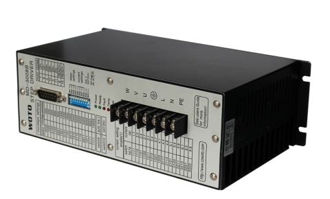


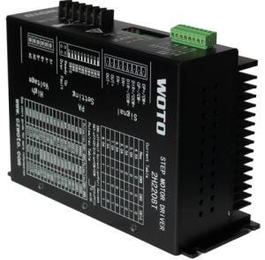
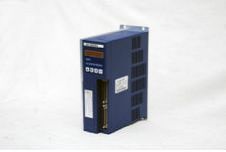
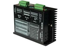
Three Phase Motor Driver MD-3008B
-
Payment


-
Origin
China Mainland
-
Minimum Order
15
-
Packing
Pieces
- Contact Now Start Order
- Description
Product Detail
MD-3008A
Characteristic :
1.use AC servo control theory , it adds full digital current loop control way .
2.The power amplifier max voltage can be up to 325V ,high speed rotation stepper motor still have output high torque .
3.With short circuit, over-voltage, under-voltage, over-temperature protection and improving functions .
4.With the function of subdivision .half current and power-down memory ability .
Many subdivision selection, control the precise location at any random condition , the min step angel can be set to 0.036° (1000steps/rev) .apply widely , by setting different phase current can be used with various motors .
stepper Motor driver Specification :
Input Power supply : | AC150V-220V -15%~+10% 50/60HZ 5.5A(MAX) |
Output Current | 1.7A~6.8A |
Drive Way | PWM constant current chopping ,three phase Sine wave output current |
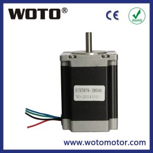
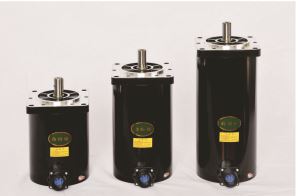
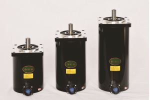
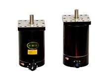
Suitable stepper motor | 90.110 and 130 series three phase stepper motor |
Ambient environment | -10?~55? 15~85%RH?No condensation. Non-corrosive, flammable, explosive, conductive gas, liquid and dust |
Keeping enviroment | -40?~+55?, <93%RH,No condensation, no frost |
Size (L*W*H) | 230*85*140 mm |
Net Weight | 1.3 Kg |
Function Selection :
set the stepper motor steps/rev ,use the DIP to set step as below :
SW1 | 0 | O | 1 | 1 | O | O | 1 | 1 |
SW2 | 1 | O | O | 1 | 1 | O | O | 1 |
SW3 | 1 | 1 | 1 | 1 | O | O | O | O |
Steps | 200 | 400 | 500 | 1000 | 2000 | 4000 | 5000 | 10000 |
Note : the fourth DIP switch is invalid .
The ninth half current function , 1 is valid , 2 is invalid .
The tenth enable funable ,1 is valid , 2 is invalid .
Output phase current :
SW5 | 1 | 1 | 1 | 1 | 1 | 1 | 1 | 1 | 0 | 0 | 0 | 0 | 0 | 0 | 0 | 0 |
SW6 | 1 | 1 | 1 | 1 | 0 | 0 | 0 | 0 | 1 | 1 | 1 | 1 | 0 | 0 | 0 | 0 |
SW7 | 1 | 1 | 0 | 0 | 1 | 1 | 0 | 0 | 1 | 1 | 0 | 0 | 1 | 1 | 0 | 0 |
SW8 | 1 | 0 | 1 | 0 | 1 | 0 | 1 | 0 | 1 | 0 | 1 | 0 | 1 | 0 | 1 | 0 |
Current | 1.7 | 2.0 | 2.4 | 2.7 | 3.1 | 3.4 | 3.7 | 4.1 | 4.4 | 4.8 | 5.1 | 5.4 | 5.8 | 6.1 | 6.5 | 6.8 |
Power interface :
1.Motor driver U.V.W. Connect with stepper motor , (1.3.5) terminal . 2.Motor driver L,N connect AC 220V .
3.Motor driver PE ,protect grounding .
Control signal :


Malfunction analysis :
Power: power supply instruction .
Ready: motor driver work normally ,green light turn on ;if motor driver work abnormally,green light will not turn on .
Fault: Malfunction or short circuit between two phase happen ,error red light turn on .
Temp: when the temperature of radiator is over 75? and light light,Temp is overheating .
Over: when the output voltage is larger than 410V , it is over-voltage.
Low: when the input voltage is smaller than 150V , it is under-voltage .
Over + Low:light at the same time,door/enable function is valid,Over + Low don’t light /enable function is invalid .
Malfunction analysis
Malfunction | Cause | Action |
Power don’t light | power supply voltage is low | Test the voltage of power supply |
Voltage of power supply connect wrongly | Test the connection of power supply | |
stepper motors don’t rotate and no holding torque | Input current signal work | make the input signal don’t work |
Wrong wire connection of stepper motor | do the correct connection | |
stepper motor don’t rotate but with holding torque | Door signal work | make the input signal work |
Input Pulse signal | Adjust the PWM and signal level | |
Stepper motors rotate irregularly | Input pulse and direction signal | Adjust the PWM and signal level |
Over-loading | Reduce the loading | |
Malfunction of stepper motor | Change the stepper motor | |
Wrong rotation direction of stepper motor | wrong phase wire connection | change the random phase wire |
input direction signal setting is wrong | change the direction setting | |
holding torque is too small | the setting of phase current is too low | Adjust the setting of phase current |
Much noise of stepper motor | Malfunction of stepper motor | Change the stepper motor |
Ready light is red | location of enable switch is wrong | check whether the setting of enable switch is correct |
Signal wire is bad | check whether signal wire is ok | |
signal wire is no signal | check whether the wire have signal | |
Fault light is on | Phase short circuit | connect the correct the motivation wire of stepper motor |
signal wire or driver wire is bad | Correct the connection | |
Pulse is with interference or the frequency of the pulse is too high | check the signal wire or low the pulse frequency | |
Temp lit | Radiator temperature >75ºC | check the setting of phase current |
check whether the fan of motor driver work | ||
Over light is on | Output voltage > 410V | check the input voltage of power supply |
Low light is on | Input voltage < 150V | check the input voltage of power supply |
Over and Low light is on at the same time | No enable signal | check the enable setting switch |
Installation :

-
High Torque Nema 23 Stepper Motor 425 Oz In 1 Pieces / (Min. Order)
-
Nema 23 Stepper Motor 1.26N.m 1 Pieces / (Min. Order)
-
Nema 23 Stepper Motor 1.89N.m 1 Pieces / (Min. Order)
-
110V Stepper Motor Driver 2H1106T 1 Pieces / (Min. Order)

-
220V Nema 34 Stepper Motor Driver 2H2208T 1 Pieces / (Min. Order)
-
Brushless Motor Driver 15 Pieces / (Min. Order)
-
2000W Servo Motor Drivers 15 Pieces / (Min. Order)
-
1500W Servo Motor Driver 15 Pieces / (Min. Order)
-
Driver Stepper Motor 2H606T 15 Pieces / (Min. Order)
-
Nema 52 Stepper Motor Driver 3008A 15 Pieces / (Min. Order)
-
Low Voltage Motor Driver 3DM683 15 Pieces / (Min. Order)
-
Motor Driver For Nema 2M423A 15 Pieces / (Min. Order)
-
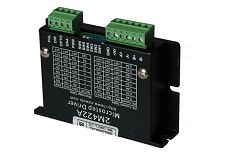
Small Stepper Motor Driver 2M422A 15 Pieces / (Min. Order)
-
220V Motor Driver 2H2208T 15 Pieces / (Min. Order)
-
Motor Driver 2H1106T 15 Pieces / (Min. Order)
-
AC Stepper Motor Driver 2H8006T 15 Pieces / (Min. Order)
-
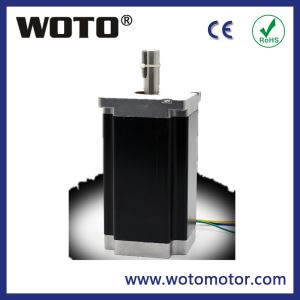
1.2 Degree Nema 52 Stepper Motor 1303P 15 Pieces / (Min. Order)
-
1.8 Degree Nema 52 Stepper Motor 130STH 15 Pieces / (Min. Order)
-
Nema 42 Stepper Motor Round Shape 1103P 15 Pieces / (Min. Order)
 Favorites

-
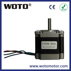
High Torque Nema 23 Stepper Motor 425 Oz In
1 Pieces / (Min. Order)
-
Nema 23 Stepper Motor 1.26N.m
1 Pieces / (Min. Order)
-
Nema 23 Stepper Motor 1.89N.m
1 Pieces / (Min. Order)
-
110V Stepper Motor Driver 2H1106T
1 Pieces / (Min. Order)
-
220V Nema 34 Stepper Motor Driver 2H2208T
1 Pieces / (Min. Order)
-
Brushless Motor Driver
15 Pieces / (Min. Order)
-
2000W Servo Motor Drivers
15 Pieces / (Min. Order)
-
1500W Servo Motor Driver
15 Pieces / (Min. Order)
-
Driver Stepper Motor 2H606T
15 Pieces / (Min. Order)
-
Nema 52 Stepper Motor Driver 3008A
15 Pieces / (Min. Order)
-
Low Voltage Motor Driver 3DM683
15 Pieces / (Min. Order)
-
Motor Driver For Nema 2M423A
15 Pieces / (Min. Order)
-
Small Stepper Motor Driver 2M422A
15 Pieces / (Min. Order)
-
220V Motor Driver 2H2208T
15 Pieces / (Min. Order)
-
Motor Driver 2H1106T
15 Pieces / (Min. Order)
-
AC Stepper Motor Driver 2H8006T
15 Pieces / (Min. Order)
-
1.2 Degree Nema 52 Stepper Motor 1303P
15 Pieces / (Min. Order)
-
1.8 Degree Nema 52 Stepper Motor 130STH
15 Pieces / (Min. Order)
-
Nema 42 Stepper Motor Round Shape 1103P
15 Pieces / (Min. Order)